Hi I am Tiankai.
Here’s the link to the video of the circuit built.https://youtu.be/sHIuKKqgosk
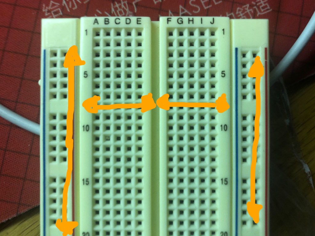
Part 1: how breadboard works
On the left and right theres power rail (beside red line) and blue rail (beside right line). Battery Positive go to power rail and negative go to ground rail.
The center areas are connect through rows. So in current flows through the same row.
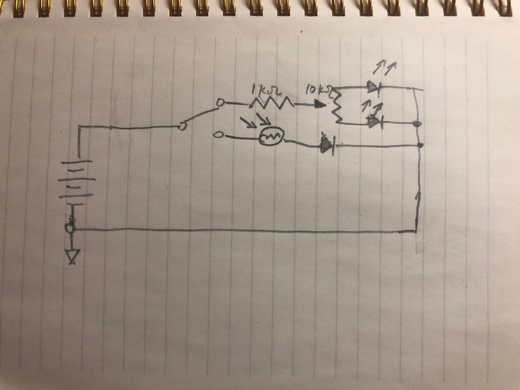
Part 2:
Below is the schematic graph:
Part three: multimeters:
So a multimeter can be used to test voltage, current, and resistance. It is composed of two test coils. the current should be flowing into red coil and goes out to black coil. And thats why red coil touch positive, and black on negative when testing. (It could go opposite, it’ll show the exact number but negative). It’s exactly precise in measuring.
Part 4: Analog Circuit Troubleshooting Notes (in memory):
1. One LED popped. I was trying to set up LED that controlled by light dependent resistance. I wired the resistance to the same row, so the flow didn’t go through it (it went through the grid, which has lower resistance). Solved by wiring to a different row.
2. Potentiometer didn’t work. I put it horizontal. Solved by putting it vertically.
Part 5 Good project ideas
Tia’s Boss amp is pretty cool. But the thing is that the recording sounds pretty much just like a distortion plugin, which really doesn’t sound like a amp, because the high frequency noise. The video sounds pretty legit though.
Paul’s guitar pedal is great, and the recording really sound like one. The oscillation really gives the warmth.
Sean Porio’s Nastifier deliver a high quality of sound too.
